

The Testing for the pan motion has been completed. The digi pot is correctly resisting voltage and this is related to the data being sent to the arduino board.
There were some initial problems with code which meant the map function which maps serial values to resistance values between 0 and 255. The serial values were only mapped from 130 to 530 this was changed to between 0 and 600 as when the data was outside of these values the resistance jumped quite significantly as the outside value was not included within the map function.
This error meant that testing was slow and wiring was double and triple checked. I was surprised to see 5v coming out of the CLK pin but i guess this makes sense. All i needed to do was be brave and trust the wiring before cranking up the voltage to 24v from the desk power supply.
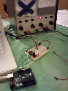
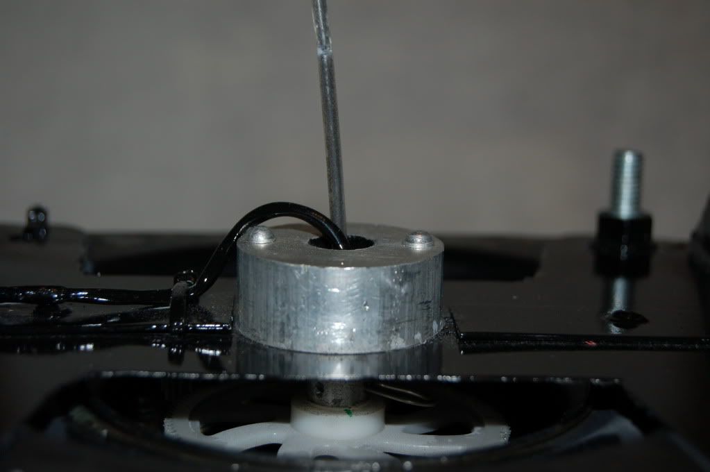
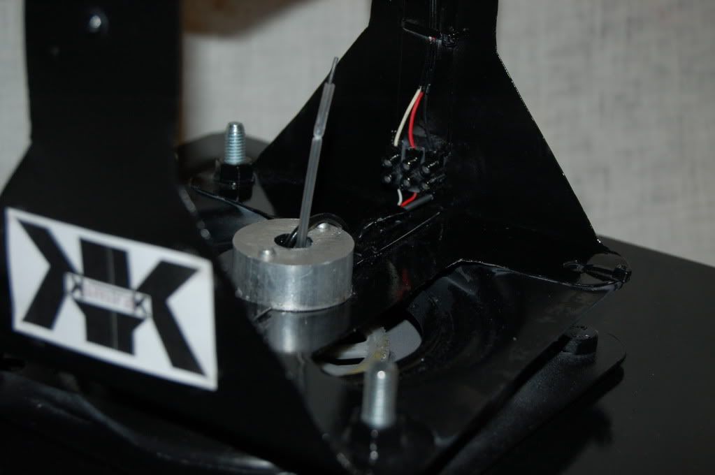
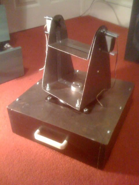
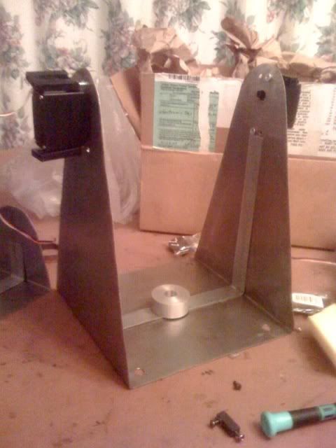
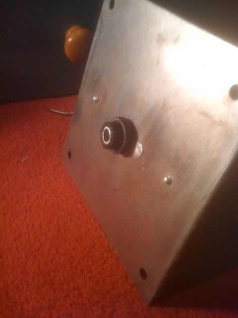
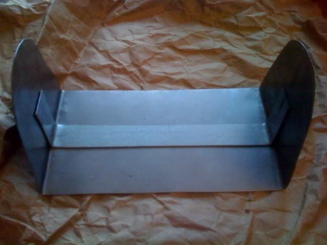
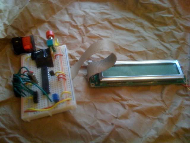
Below are some photos of the test setup. The next part is to copy and tailor the code for the tilt function.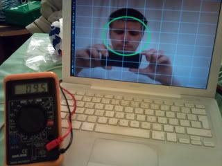
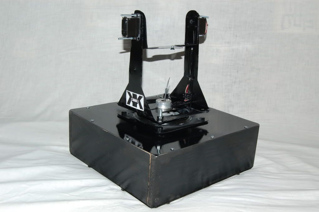
A conversion using digital potentiometers has been completed for the pan motion of a larger rig. This rig can hold a broadcast camera easily. The control for the motors is achieved by sending an analogue voltage to the camera rig head.
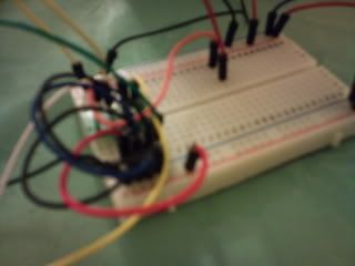
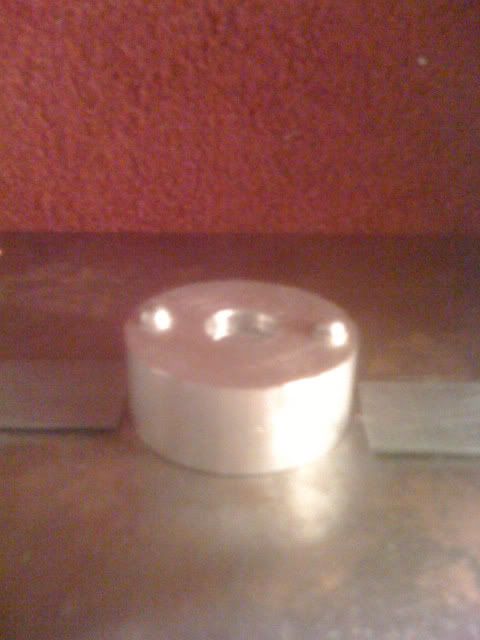
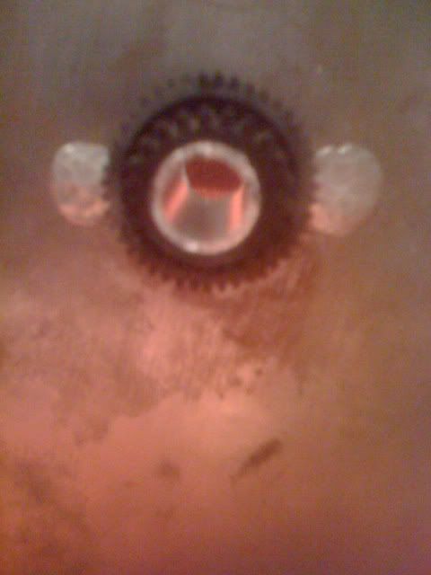
here is a picture of the MSOP digi pot on a breadboard adaptor taken from a microscope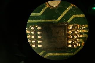
These volts are 24v for one direction 0v for the opposing direction and 12v for stop.
The conversion was completed today for the pan motion, so one digi pot has been used. Another will be used for the tilt motion.
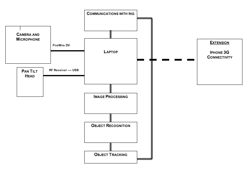
The digital pot works in a similiar way to physical pots like a standard volume pot. The digital pot receives a negative and postive voltage and a variably resisted output is achieved by controlling a wiper in software code. The output of the face tracking software takes the pixel coordinates for the position of a circle within the frame. This is then converted to Hex and sent over USB to an Arduino kit using the ATMEL ATmega 328 chip. A separate piece of code runs on this chip which converts the hex back to decimal coordinates which are mapped to a level of resistance.
The digipot can take a maximum of 30v, 24v of which is divided between the two terminals A and B, or negative and positive, on the chip. Depending on where the circle is in the facetracking software, determines the level of resistance for the analogue voltage which should move the rig.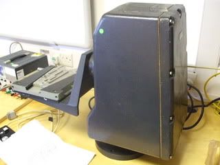
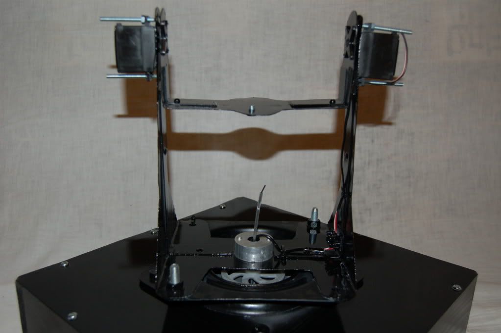
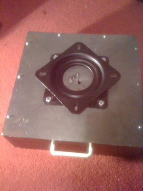
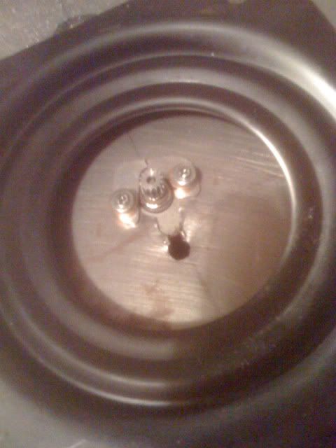
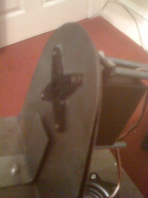
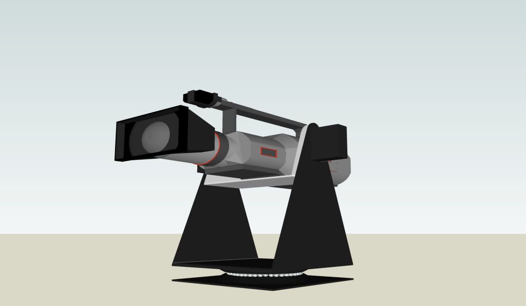
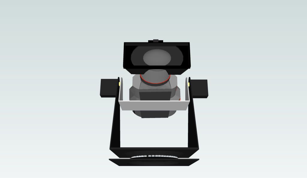
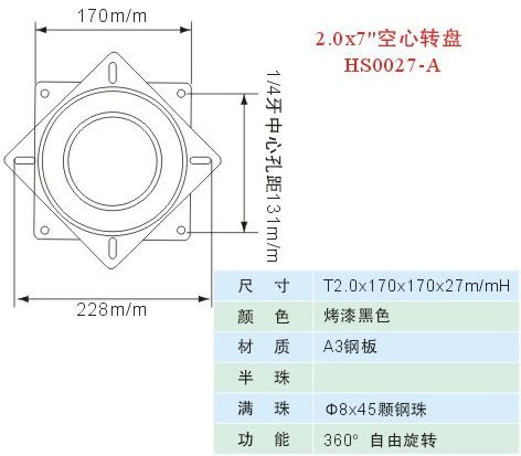
This is the pan and tilt head which requires variable voltage from a 24v source. In this project I am using a digipot to resist the voltage in software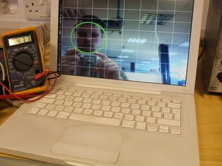
You can see when my face is situated in the left of frame, 4.77v is output from the digipot wiper.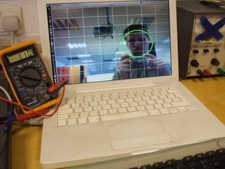
When my face is situated in the right of frame, 1.1v is output from the digipot wiper. This proves the code is working for a low voltage. Now a 24v supply needs to be connected.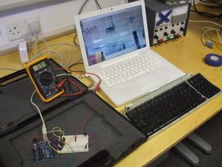
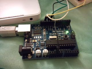
Here is the setup consisting of a laptop running xcode and the facial tracking software, an arduino running different code, and a digipot being output to a voltmeter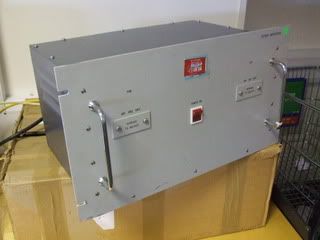
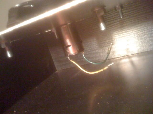
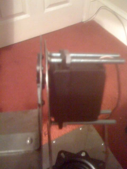
This is the amplifier which drives the motors inside the pan and tilt head
UPDATE The system is now operational with facial tracking working from a stationary camera. the Head mimics the subjects movements providing that the software recognises a face. The pixel mapping works and is mapped to the angle of the servos.
The next step is to introduce a laplace transform which will dampen or smooth the voltage steps to give a smoother overall movement. This project will also be linked with a stereo pair of cameras for use with stereoscopic 3D applications.
Microchip can now control a servo through the use of terminal and directional buttons from the laptop. This needs to be put into code form but shows that the communication between laptop and MCU is working.- Reducing the weight of the rig has been completed
- Painting has been completed
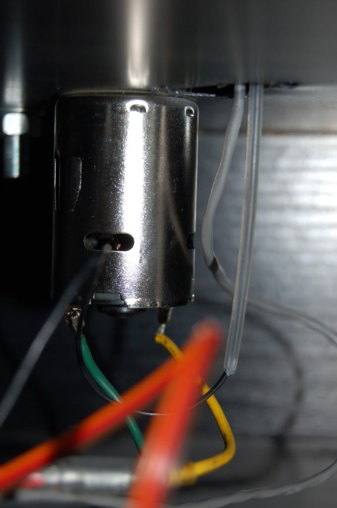
- Cabling in the servo is finished
- Starting to work on controller electronics
- Software is taking longer than expected - Have enlisted the help of a tutor
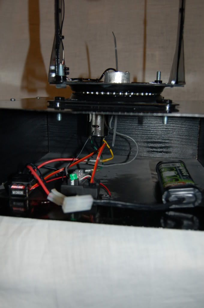
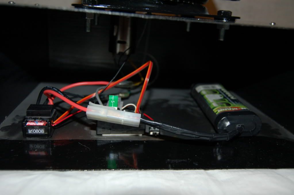
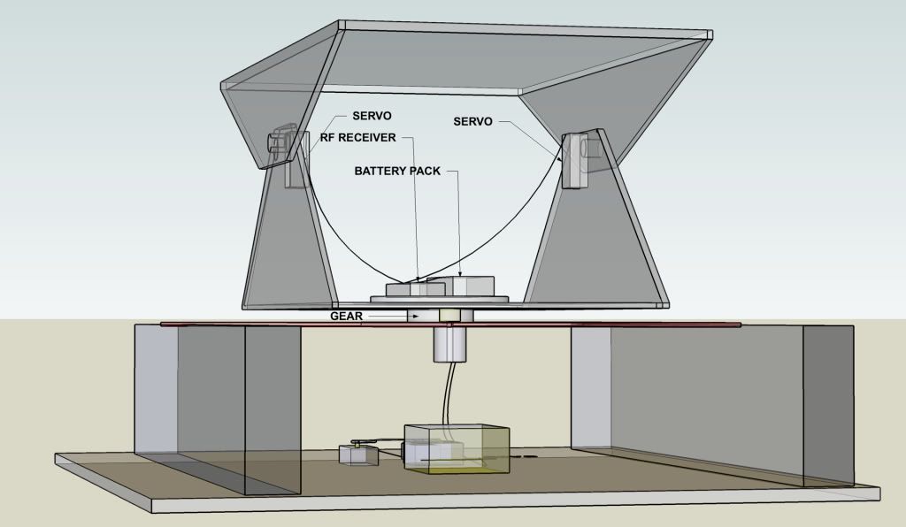
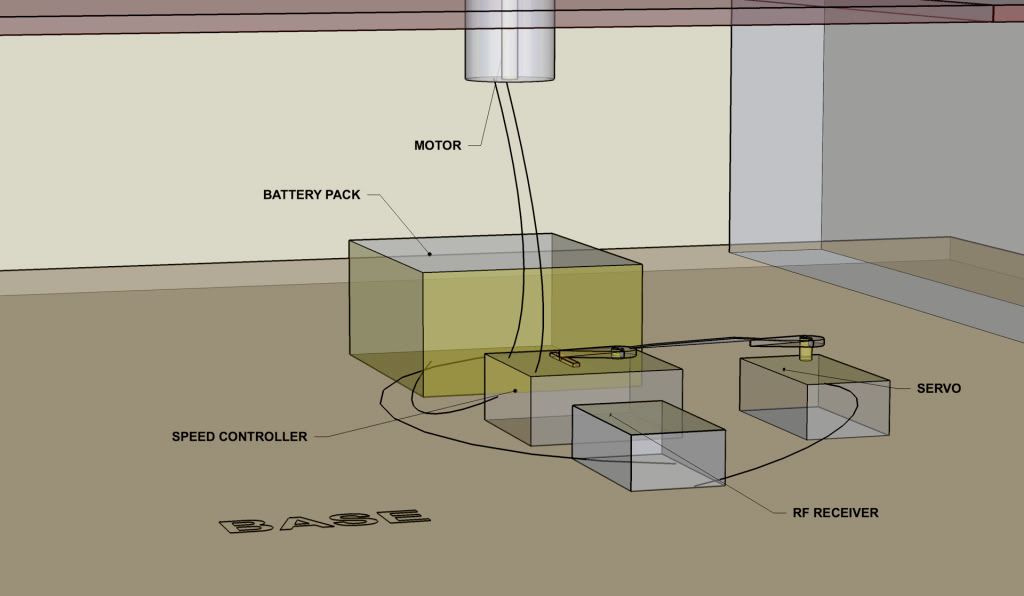
- Camera rig now has an electronic speed controller (ESC) for the pan function. This has also stopped the over heating problem with the old mechanical speed controller.
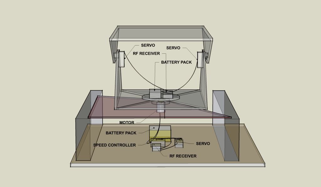
- The rig is now fully remote controlled.
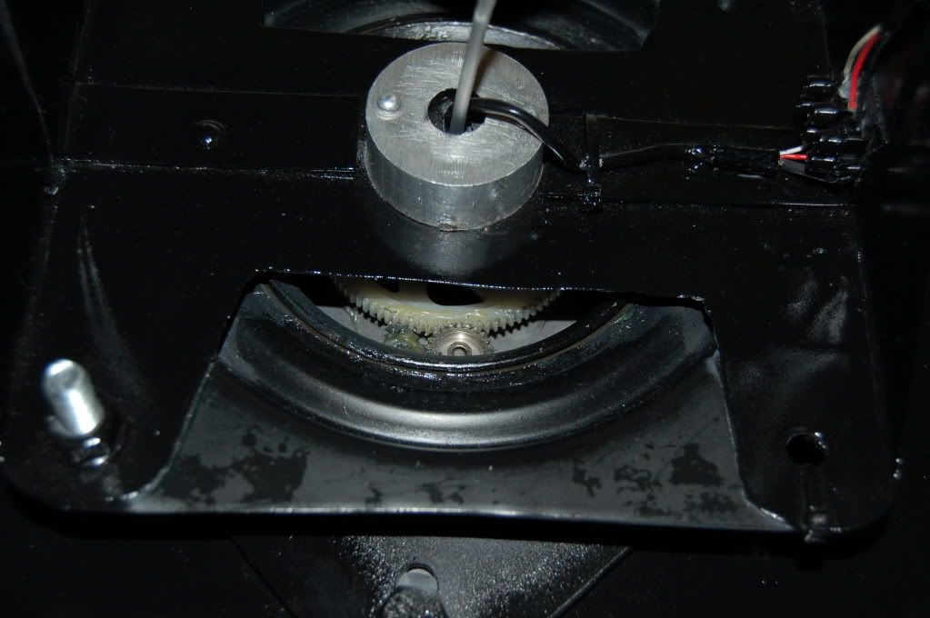
- New gearing mechanism made. Old mechanism was too small and couldnt take the load. The gear was also being stripped. New mechanism fits onto the end of the pipe with a split pin pushed through holes that were drilled in the pipe and gear. The gear now doesnt strip and grease has been applied
- Having interference issues between the two channels. Trying to see if its the power from the transmitter maybe the batteries are low.
Last Updated 22nd JUNE 2010


Subscribe to:
Post Comments (Atom)


2 comments:
Post a Comment