

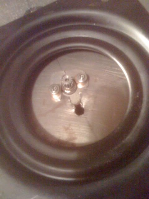
- Voltages measured for RF transmitter. These correspond to the type of signal sent to the RF Receiver which then outputs a voltage telling the servos what position to be in.
2.2v for full left, 2.6v for middle and 2.9v for full right. The potentiometer has a constant voltage of 5.15v and the variable control voltages and also a ground.
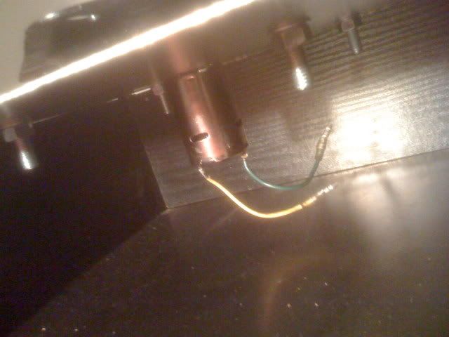
For the Receiver the voltages are:
Data Cable (white) sends variable voltages of 0.28v for full left, 0.4v for middle, and 0.51v for full right. The power cables (+ and -) supply constant voltages to the servos. When the transmitter is off, no data voltage is generated.
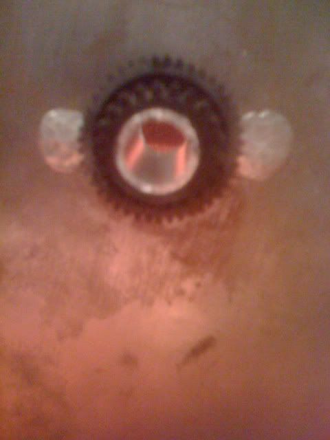
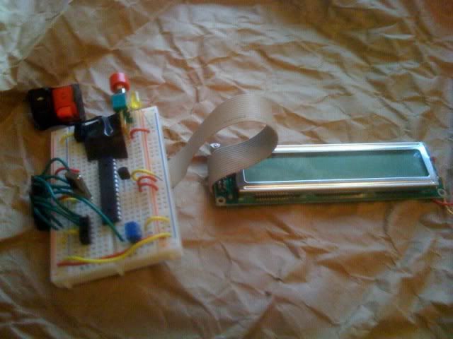
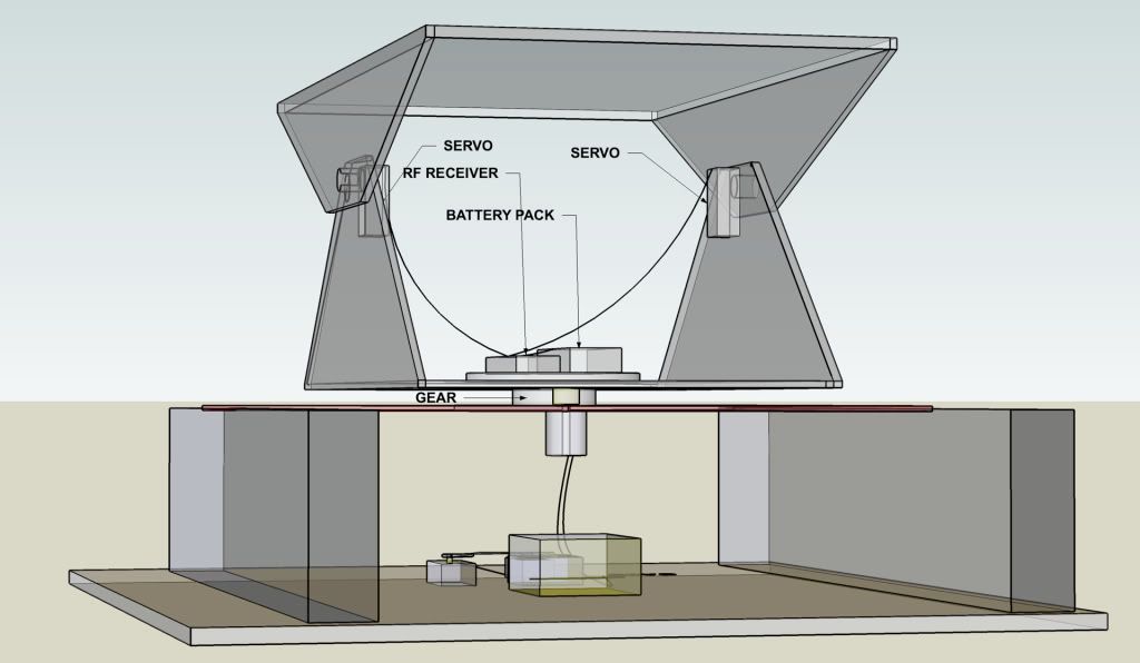
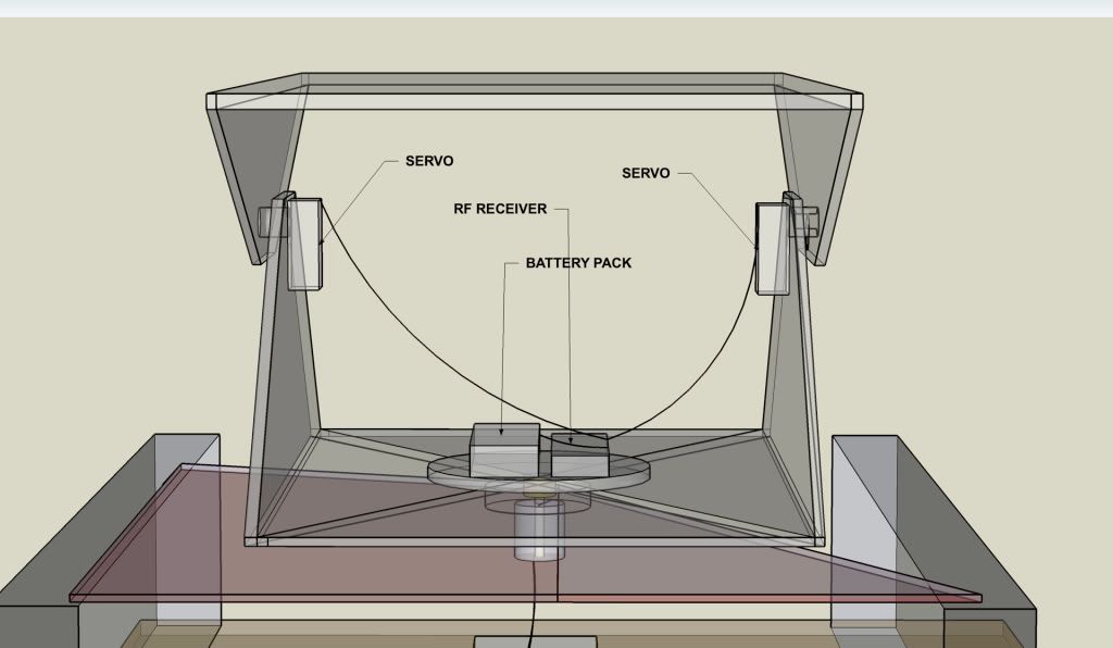
- The way in which the transmitter is controlled is by linking the microchip from nerdkits to the variable voltage output on the transmitter. The chip will generate a PWM (pulse width modulated) signal out to a capacitor which will charge and discharge with respect to the rate of PWM. This charge and discharge process will give the required voltages for the transmitter to produce its original signal when the potentiometer is altered manually.
- The transmitter requires a minimum of 8.55v to function. So could possibly run off a 9v battery (probably not for very long).
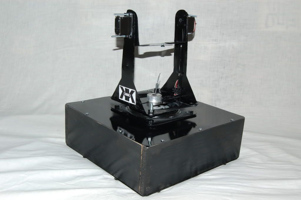
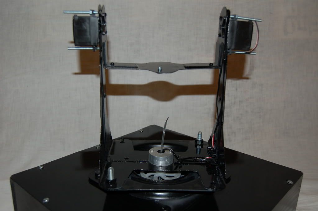
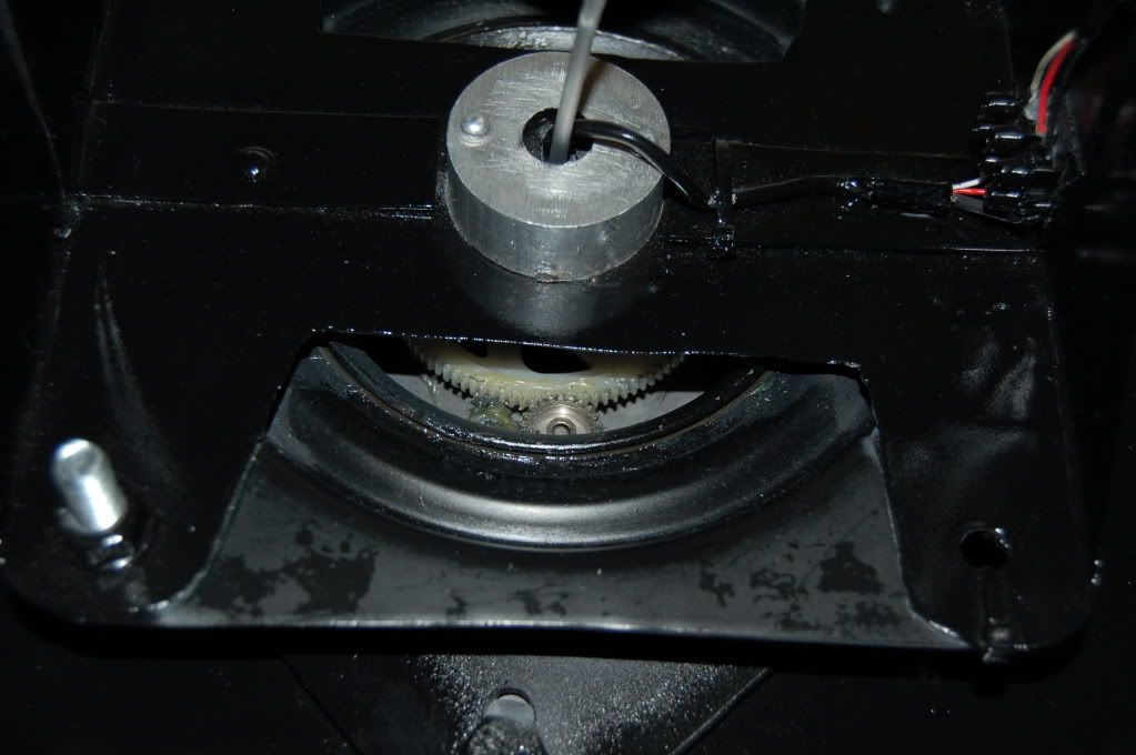
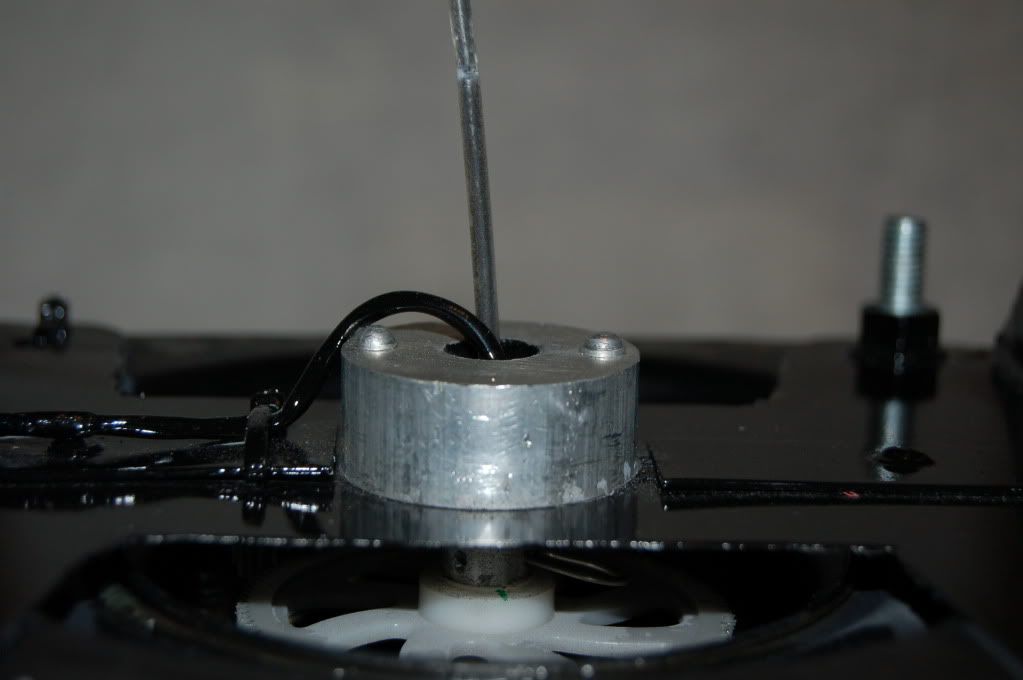
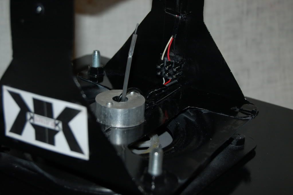
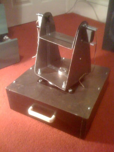
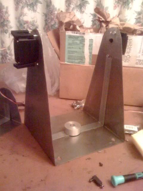
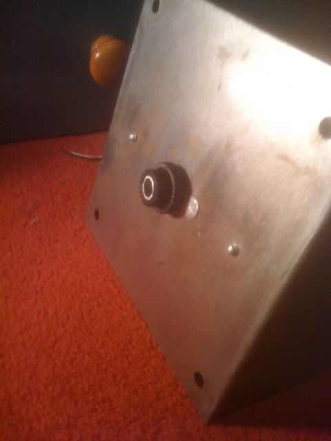
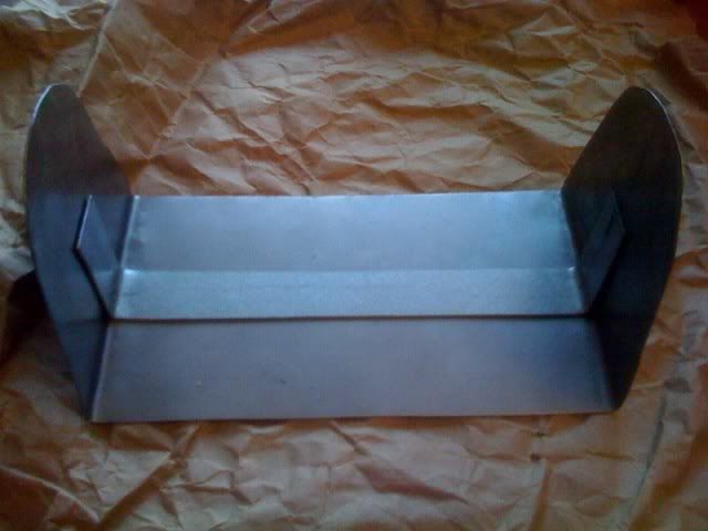
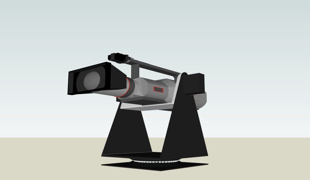
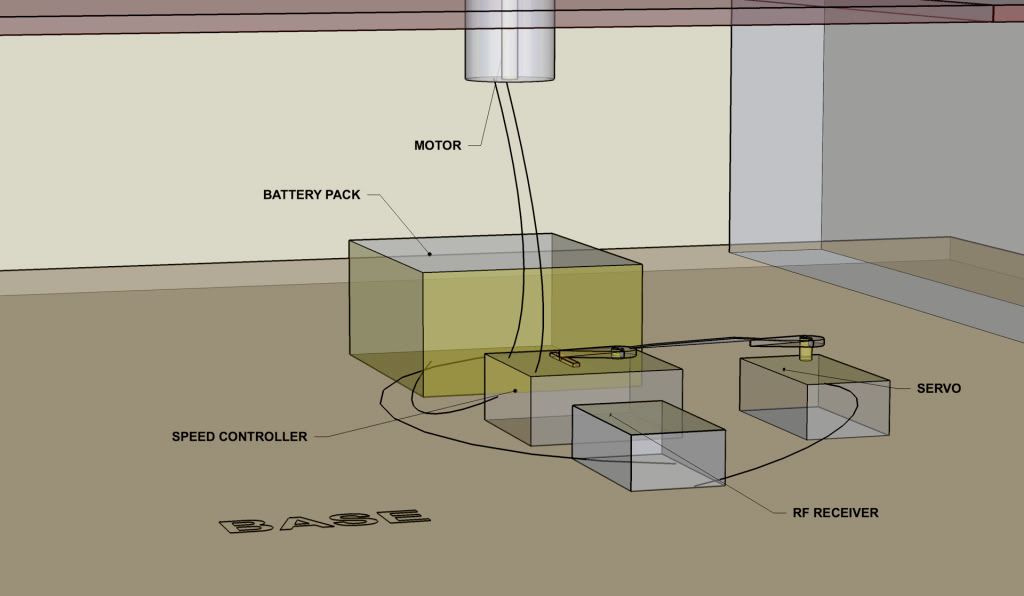
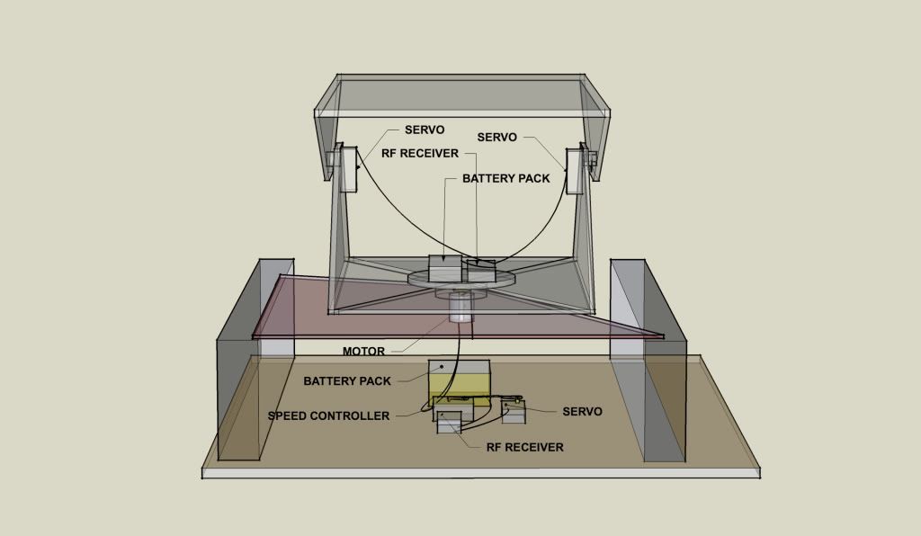
- The rig needs to be made lighter in weight as the motor is overheating. The process of cooling will not be enough as the load is probably too heavy for the motor anyway. This will be lightened by cutting out sections of the rig.


No comments:
Post a Comment